 Skip to content
 Solid Heating Solutions for Industrial Applications
Engineering-Driven Thermal Design for Solid Materials
Industrial solid heating systems require precise power sizing, uniform heat distribution, material-specific ramp control, and engineered safety design. This guide provides a complete engineering framework for designing reliable, high-efficiency solid heating systems used in manufacturing, processing, tooling, and heavy industry.
Introduction to Solid Heating in Industrial Systems
Solid heating refers to the controlled transfer of thermal energy into solid materials such as:
- Metal blocks
- Injection molds
- Dies and tooling
- Platens and plates
- Structural components
- Valves and mechanical housings
In industrial environments, solid heating is primarily achieved through conduction, where the heating element is embedded into or tightly attached to the solid body.
Comprehensive Heating Solutions
We categorize our solid heating solutions by the method of thermal transfer and physical installation.


Tubular Heaters (Calrod)
Best for: Surface heating of plates, Grooved embedding, Cast-in assemblies, Irregular solid shapes.
- Custom bending geometry
- Mechanical durability
- Medium-to-high watt density

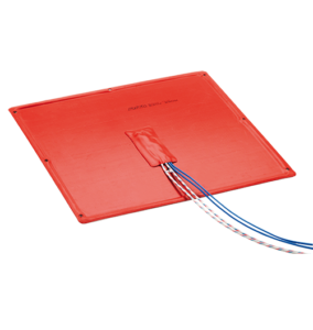
Silicone pad heater
Best for: Flat solid surfaces, Freeze protection, Equipment panels, Low-temperature solid heating.

heating strip
Best for: HVAC Supplemental/Emergency Heat,Industrial Surface Heating,Process Air Heating,Food Service,Defrosting
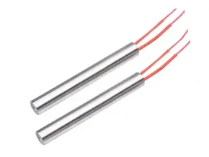
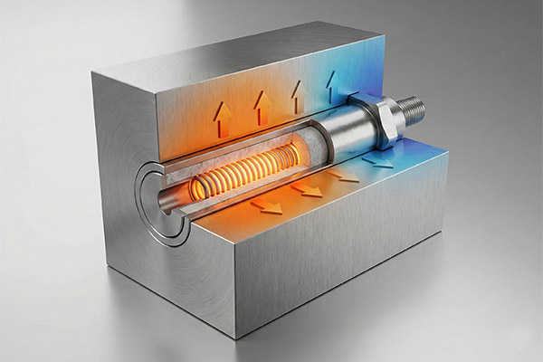
Cartridge Heater
Best for: Injection molds, Metal dies, Aluminum/steel blocks, High precision heating zones.
- High watt density capability
- Compact cylindrical design
- Excellent heat transfer through tight fit
- Optional built-in thermocouple
Engineering Note:Hole tolerance should follow H7 standard to ensure optimal thermal conduction and prevent air gaps.


Infrared Heaters
Best for: Surface heating without contact, Coating and drying processes, Sensitive solid materials.
Core Tech: Maximizing Transfer
In solid heating, air is the enemy. Our manufacturing process focuses entirely on eliminating internal air gaps and ensuring tight external fits.
The Physics of Reliability
Material Specifications
| Component | Material Grade |
|---|---|
| Sheath | SS304 / SS316L / Incoloy 800 (for >750°C) |
| Insulation | High-Purity MgO (>99%) |
| Resistance Wire | NiCr 80/20 (Germany/Japan) |
| Lead Wire | Fiberglass / Teflon / Silicone |
Technical Specifications
Parameters vary by heater type. Custom designs can exceed these limits.
| Feature | Cartridge (HD) | Mica Band | Silicone Mat | Ceramic Strip |
|---|---|---|---|---|
| Max Temp | 750°C (1380°F) | 450°C (842°F) | 200°C (392°F) | 700°C (1290°F) |
| Watt Density | 25 W/cm² | 4 W/cm² | 0.8 W/cm² | 6 W/cm² |
| Diameter/Size | Ø 2mm – 50mm | Ø 25mm – 1000mm | Custom Shapes | Width: 20mm+ |
| H7 Tolerance? | YES (±0.02mm) | N/A | N/A | N/A |
| Voltage | 12V – 480V | 24V – 480V | 12V – 240V | 110V – 480V |
Note on Variable Wattage: We offer Distributed Wattage (Variable Pitch) winding to compensate for heat loss at the extremities of the mold.
Termination Options
The failure point is rarely the element; it is usually the lead exit. Select based on your stress factors.
Swaged-In Leads (Internal)
Best for: High Vibration / Movement.
Lead wire connects to pin inside the core. Eliminates rigid connection points.
Crimped-On (External)
Best for: Static Heating.
Cost-effective. Easy to repair. Suitable for temps < 250°C at exit.
Right Angle Block
Best for: Confined Spaces.
Prevents sharp cable bending that compromises insulation.
Armor Cable / Braid
Best for: Abrasion Risks.
Stainless steel hose provides mechanical protection against crushing.
Engineer's Installation Tips
Critical Warning
“A 0.1mm gap can reduce heater life by 50%. Proper fit is the single biggest factor in longevity.”
Maintenance Protocol
Hygroscopic Alert: MgO powder attracts moisture. If stored >6 months, perform a “Soft Start” (half-voltage for 10 mins) to evaporate moisture.
Do’s and Don’ts
- DO: Optimize the Fit (H7). Drill/ream holes to ISO H7 tolerance (e.g., 10.00 – 10.015mm).
- DO: Use Thermal Paste Sparingly. A thin layer helps; excess paste carbonizes and causes shorts.
- DON’T: Run in Open Air. High-density heaters must dissipate heat into metal or they will fail in seconds.
- DON’T: Pull by Leads. Always handle by the sheath.
RFQ Checklist
Please have these data points ready when requesting a quote to ensure rapid engineering:
- Heater Type: (Cartridge, Band, Strip, etc.)
- Dimensions: (Diameter/Width, Length)
- Voltage & Wattage: (e.g., 230V / 500W)
- Operating Temp: (Target temp of solid mass)
- Medium: (Steel, Aluminum, Brass?)
- Termination: (Swaged-in, Crimped, Plug)
- Lead Length: (Standard is 250mm)
- Specials: (Thermocouple J/K, Variable Pitch)
Contact Us
Please feel free to contact us with any questions, and we will dispatch a professional engineer to assist you.
Engineering Fundamentals of Solid Heating
Dominant Heat Transfer Mechanism
Solid heating systems are primarily governed by conduction. Unlike fluid heating, thermal energy must penetrate mass through internal molecular transfer.

q = heat transfer rate (W)
k = thermal conductivity (W/m·K)
A = contact area (m²)
dT/dx = temperature gradient
Design Implication:
• Higher conductivity materials heat faster internally.
• Low conductivity solids require multi-zone heating.
• Contact pressure significantly affects heat transfer.

Contact Thermal Resistance
Real systems include surface roughness. Microscopic air gaps create resistance.

To reduce contact resistance:
- Machine flat surfaces
- Use thermal grease (where allowed)
- Increase mechanical clamping force
- Use cast-in heater integration
Engineering Power Calculation Methodology
Required Energy Calculation
Q=m⋅c⋅ΔT
Where m = mass (kg), c = specific heat (J/kg·K), and ΔT = temperature rise (K).
Q = 80 × 490 × (400 – 25)
Q = 80 × 490 × 375
Q ≈ 14,700,000 J
Example Engineering Case:
Heating 80 kg carbon steel block
• Initial temp: 25°C | Target temp: 400°C
• Time required: 30 minutes
• Specific heat of steel ≈ 490 J/kg·K
Convert to power (30 min = 1800 s):
P = Q / t = 14,700,000 / 1800
P ≈ 8,167 W (8.2 kW)
Engineering Rule: Add 15–30% safety margin → Select 10 kW system.
Heat Loss Estimation
Real systems lose heat through convection and radiation.

h = convection coefficient
ε = emissivity
σ = Stefan-Boltzmann constant
For high-temperature steel (>300°C), radiation becomes dominant.
Design Implication:
Insulation is mandatory above 200°C. Bare metal heating wastes 20–40% of energy.
Material-Specific Engineering Guidelines
| Material | Thermal Conductivity (W/m·K) | Specific Heat (J/kg·K) | Risk Factor |
|---|---|---|---|
| Aluminum | 205 | 900 | Fast surface heating |
| Carbon Steel | 50 | 490 | Moderate expansion |
| Stainless Steel | 16 | 500 | Hot spot risk |
| Cast Iron | 55 | 460 | Crack sensitivity |
| Ceramic | 2–5 | 800 | Thermal shock risk |
| Graphite | 150 | 710 | Oxidation risk |
Aluminum Implications
• High conductivity
• Allows higher power density
• Requires tight temperature control
Stainless Steel Implications
• Low conductivity
• Multi-zone heating recommended
• Avoid localized cartridge heaters without distribution analysis
Ceramic Implications
• Very low thermal shock tolerance
• Ramp rate must be controlled below 2–3°C/min
Heating Element Selection Matrix
Power Density Comparison
| Heater Type | Max W/cm² | Best For | Limitation |
|---|---|---|---|
| Cartridge Heater | 20–35 | Mold blocks | Risk of burnout if misfitted |
| Tubular Heater | 5–15 | Plates | Slower response |
| Cast-In Heater | 3–10 | Large blocks | High tooling cost |
| Mica Band Heater | 3–8 | Flat surfaces | Lower durability |
| Silicone Heater | 1–5 | Low temp solids | < 250°C typical |
Selection Logic Flow:
1. Determine material conductivity ➔ 2. Calculate required power ➔ 3. Determine allowed ramp rate ➔ 4. Select power density ➔ 5. Decide control zoning.
Thermal Uniformity Engineering
Uniform heating prevents stress cracks and dimensional distortion.
Multi-Zone Heating
Large solids (>30 kg) require:
Heating large solids (masses >30 kg) presents a significant challenge: thermal lag. Achieving surface-to-core temperature consistency requires more than raw power; it requires a segmented, intelligent control strategy to prevent localized overheating and structural stress.
Core System Requirements
To maintain tight tolerances in heavy tooling or structural components, the system must integrate three critical engineering pillars:
Independent Heating Zones: Segmented heating elements (Tubular or Cartridge) allow for localized wattage adjustment, compensating for heat loss at edges and corners.
Localized Feedback (Multiple Thermocouples): Each zone must have a dedicated sensor placed near the heat source to monitor real-time thermal gradients.
Dedicated PID Control: A “Master-Slave” or independent PID loop per zone ensures the controller adjusts power output based on specific local demand rather than a single average temperature.
Performance Benchmarks
We engineer systems to meet the following industry-standard uniformity targets:
| Application Type | Uniformity Target | Critical Focus |
| Precision Tooling | ±3°C | Preventing dimensional inaccuracy and thermal expansion mismatch. |
| Structural Parts | ±5°C | Eliminating internal stresses and ensuring consistent material grain structure. |
Layout Engineering
Core Design Strategies
Edge Compensation: Increase watt density at the perimeter to offset higher convective and radiative losses.
Symmetrical Layout: Mirror heater placement across central axes to ensure uniform thermal expansion and prevent structural warping.
Peripheral Loading: Avoid center-heavy heating to prevent core “heat islands” and sluggish PID response.
Loss-Point Zoning: Concentrate heating elements near high-loss areas like mounting brackets or bolted interfaces.
Implementation Guidelines
| Principle | Technical Action | Target Outcome |
| Edge Bias | Higher $W/cm^2$ at boundaries | Flat temperature gradient |
| Symmetry | Balanced geometric spacing | Zero mechanical distortion |
| Distributed Heat | Minimized source-to-core distance | Reduced thermal lag |
| Thermal Compensation | High-density zoning at heat sinks | Localized loss neutralization |
Real Industrial Case Studies

Injection Mold Preheating: Eliminating 40°C Thermal Lag
Target Application: Plastic Injection Molding Substrate
Material: Tool Steel Block (120 kg)
The Engineering Challenge
During the preheating phase, a 120 kg tool steel mold exhibited a severe 40°C thermal lag between the heated surface and the internal core. This temperature gradient disrupts polymer melt flow, leading to short shots, dimensional warping, and increased defect rates.
The Technical Solution
To force rapid, uniform heat penetration through the high-mass steel block, we implemented a localized, multi-zone heating strategy:
Heating Elements: Machined and installed 12 high-density cartridge heaters. High watt-density elements ensure maximum heat transfer into the surrounding steel without premature element burnout.
Thermal Control: Divided the tooling block into 3 independent control zones to independently manage the heat output at the core versus the edges.
Feedback Loop: Embedded high-accuracy thermocouples directly adjacent to the cartridge heaters for precise, real-time PID temperature regulation.
Quantifiable Results
Thermal Uniformity: Gradient reduced from 40°C to an absolute tolerance of ±2.5°C across the entire 120 kg block.
Production Efficiency: Optimized heat transfer reduced the total molding cycle time by 18%.

Steel Plate Stress Relief: Preventing Thermal Cracking
Target Application: Heavy Metal Fabrication Substrate
Material: 40 mm Thick Steel Plate
The Engineering Challenge
Stress relieving heavy steel plates requires precise thermal gradients. Rapid, uncontrolled heating caused the surface of the 40 mm plate to expand faster than the core, inducing severe internal thermal stress and resulting in structural cracking.
The Technical Solution
We engineered a controlled thermal environment to synchronize the expansion rate of the steel’s core and surface:
Programmable Ramp Rate: Programmed the heating controller to a strict 4°C/min temperature ramp limit. This slow, methodical wattage delivery prevents temperature shock.
Thermal Retention: Deployed a custom, high-temperature ceramic fiber insulation blanket over the setup. This eliminates ambient heat loss, stabilizing the thermal gradient across the 40 mm thickness.
Quantifiable Results
Defect Elimination: Completely eliminated thermal cracking and material fatigue.
Process Reliability: Sustained a 100% structural yield across 50 consecutive production cycles.
Heating Element Failure Modes & Risk Analysis
Understanding why heating elements fail is critical for extending lifespan and maximizing industrial process efficiency. Below is a technical breakdown of common failure modes, their root causes, and engineered prevention strategies.
Over-Power Density Burnout
Root Cause: Operating an element at a watt density that exceeds the system’s capacity for heat dissipation. This traps heat internally, pushing the core temperature past the dielectric breakdown limit of the Magnesium Oxide (MgO) insulation, resulting in a short circuit or complete sheath melting.
Prevention Strategies:
Precision Machining: Maintain a strict H7 fit tolerance between the cartridge heater and the bore hole to maximize surface-to-surface thermal transfer.
Complete Insertion: Ensure the entire heated length of the element is 100% embedded within the conductive medium.
Eliminate Air Gaps: Air acts as a thermal insulator. Minimizing clearance prevents trapped air from causing localized overheating.
Thermal Shock Cracking
Root Cause: Extreme temperature gradients occurring when the heater surface rapidly expands while the internal core or surrounding tooling remains cold. This mechanical stress fractures the outer sheath or breaks the internal resistance wire.
Prevention Strategies:
Controlled Ramp Programming: Utilize PID controllers with soft-start capabilities to gradually increase voltage and allow uniform thermal expansion.
Preheating Stages: Implement a low-voltage bake-out or preheat cycle to stabilize temperatures before applying full operational power.
Multi-Point Monitoring: Install distributed thermocouples to track both surface and internal temperature gradients in real time.
Hot Spot Formation
Root Cause: Poor geometric layout of the heating elements or embedding them in materials with low thermal conductivity. This restricts uniform heat flux and creates localized zones of excessive temperature.
Prevention Strategies:
Thermal Modeling (FEA): Execute Finite Element Analysis during the tooling design phase to accurately predict heat flow and optimize heater placement.
Zonal Power Control: Specify distributed wattage heaters (e.g., higher watt density at the ends, lower in the middle) or use independent control zones to dynamically compensate for areas with high heat loss.
Temperature Control Architecture
Sensor Selection
| Sensor Type | Accuracy | Best Use Case |
|---|---|---|
| K-Type Thermocouple | ±2°C | High temp environments |
| PT100 RTD | ±0.1°C | Precision tooling |
| Infrared (IR) | Non-contact | Moving parts / surfaces |
Control Strategy
PID tuning is essential for stability.
SSR (Solid State Relays) preferred for fast switching.
Safety high-limit controller is mandatory.
Safety Additions Required:
Over-temperature cutoff, thermal fuses, and redundant sensors.
FAQ – Solid Heating Applications
Q1: How do I calculate the correct heater wattage for solid materials?
To determine the precise wattage required, use the fundamental thermodynamic equation:


- Calculation Variables: Base your baseline calculation on material mass, specific heat, target temperature rise, and required heat-up time.
- System Efficiency & Margin: Always factor in a 20% to 30% safety margin to account for conduction and convection heat losses.
- Engineering Warning: Never oversize wattage beyond 30%. Excessive power density causes rapid short-cycling, leading to premature failure of both the heater and the contactor.
Q2: What causes premature solid heating element failure?
Heater degradation is almost exclusively driven by poor heat dissipation or operational misuse. The four primary failure modes are:
- Excessive Watt Density: Specifying a surface load ($W/cm^2$ or $W/in^2$) that exceeds the target material’s thermal conductivity limits, causing internal resistance wire burnout.
- Poor Thermal Contact: Air gaps between the heating element (e.g., a cartridge heater) and the insertion bore act as thermal insulators. Maintain a tight machine tolerance—typically 0.001″ to 0.005″ clearance.
- Dry Firing: Operating liquid-specific or immersion heaters in open air rapidly destroys the metal sheath (e.g., SUS304, Incoloy 800) and internal dielectric insulation.
- Inadequate Temperature Control: Relying on simple on/off thermostats instead of PID controllers, or improper thermocouple placement, resulting in severe thermal overshoot.
Q3: Is thermal insulation strictly necessary for solid heating applications?
Yes. Integrating industrial insulation (e.g., ceramic fiber, calcium silicate) around the heated load is critical for thermodynamic efficiency and system longevity.
- Energy Efficiency: Drastically reduces ambient heat loss, directly lowering continuous kW consumption and operating costs.
- Temperature Uniformity: Prevents thermal gradients and cold spots across the heated mass, ensuring consistent process or product quality.
- Heater Lifespan: Reduces the required duty cycle, minimizing thermal fatigue on the internal resistance alloy (e.g., NiCr 80/20).
Q4: Does a higher watt density always result in faster heating?
- No. Heat transfer rates are gated by the thermal conductivity of the target material, not solely by the heater’s output capacity.
- If the heater’s watt density exceeds the material’s ability to absorb and conduct heat away from the sheath, the internal temperature of the element will spike.
- This causes the high-purity Magnesium Oxide (MgO) powder to lose its dielectric strength, resulting in a short circuit and rapid failure. Always match the watt density to the specific material (e.g., use low density for plastics, high density for aluminum or steel blocks).
Q5: What is the expected lifespan of industrial solid heating elements?
Lifespan is highly variable and depends entirely on application parameters, sheath material selection, and operational environment. Under optimal installation and PID control:
- Cartridge Heaters: 3,000 to 20,000 hours.
- Tubular Heaters: 5,000 to 25,000 hours.
- Cast-in Heaters: 20,000+ hours.
- Key Variable: Maximum operational life is achieved by ensuring precise bore tolerances, utilizing solid-state relays (SSRs) with PID controllers, and avoiding extreme thermal shock.
Q6:How to determine safe power density?
Power density depends on: Material conductivity, Contact fit tolerance, and Operating temperature.
General safe limits:
- Steel contact cartridge heater: ≤ 25 W/cm²
- Aluminum: ≤ 35 W/cm²
- Cast iron: ≤ 18 W/cm²
Q7: How do I prevent internal thermal stress during heating?
Thermal stress causes warping and cracking due to uneven thermal expansion. Prevent it by:
- Limiting Ramp Rate: Program a slow, controlled heat-up phase via a PID controller to allow heat to penetrate the core.
- Ensuring Uniform Distribution: Place heaters symmetrically to match the target load’s geometry.
- Avoiding Single-Point Heating: Distribute total wattage across multiple, lower-density heaters instead of forcing power through a single insertion point.
- Monitoring Core Temperature: Embed thermocouples deep inside the mass to track internal heat, rather than relying solely on surface sensors.
Q8: How can I accurately calculate heating time?
Theoretical calculations assume perfect insulation, which does not exist in real-world field conditions.
- The 1.2–1.5 Multiplier: Calculate the theoretical minimum heating time (based on mass, specific heat, and wattage), then apply an empirical correction factor of 1.2 to 1.5. This compensates for ambient heat loss and imperfect thermal contact.
- Physical Validation: Always conduct a physical ramp-test under actual production conditions to establish your exact time-to-temperature baseline.