 Skip to content
 Silicon Carbide Heating Elements
From the customer’s perspective: predictable heat, predictable cost.Our recrystallized SiC (RSic) elements deliver fast heat-up, stableoperation up to 1,600°C, and straightforward integration with you!existing power gear.
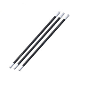
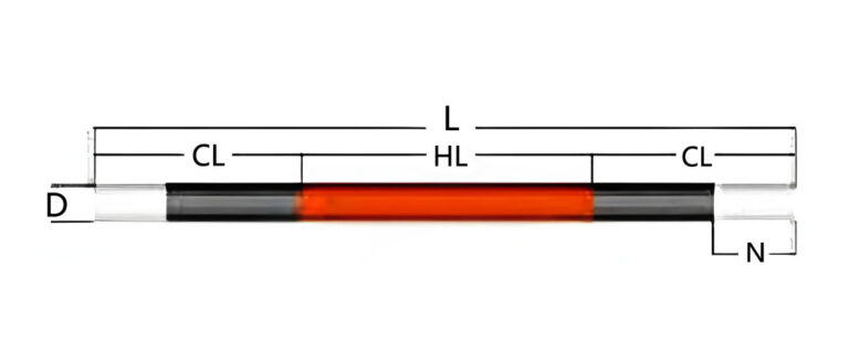
Straight / Rod
The all-rounder for box, tube, and muffle furnaces. Simplest wiring and easiest retrofit into existing fixtures.
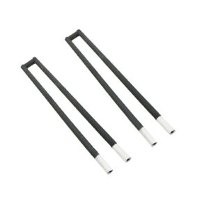
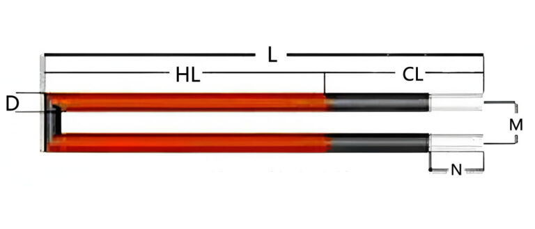
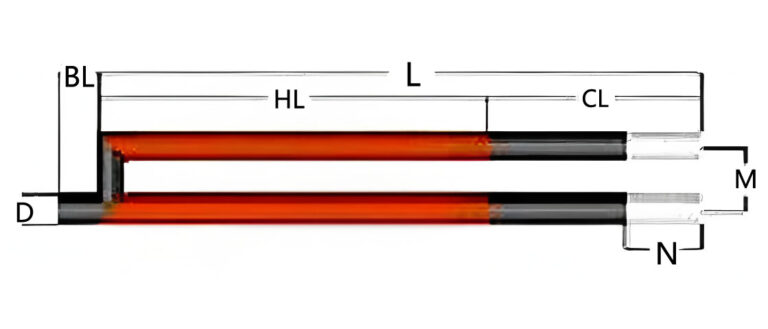
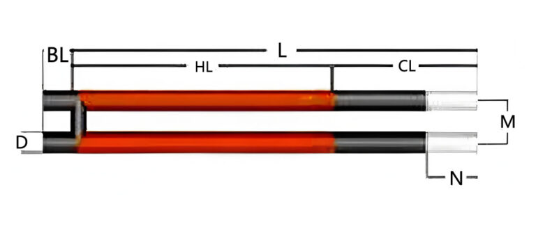
U-Shape
Two hot legs with a cool bridge for compact chambers or where power density must focus in the hot face.

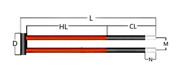
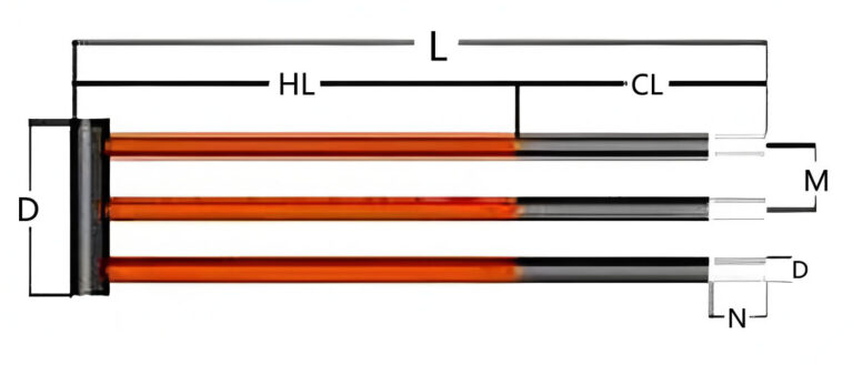
W-Shape
Three-leg design to balance voltage and current across larger hearths and tall stacks.
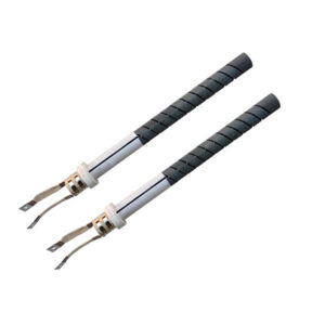
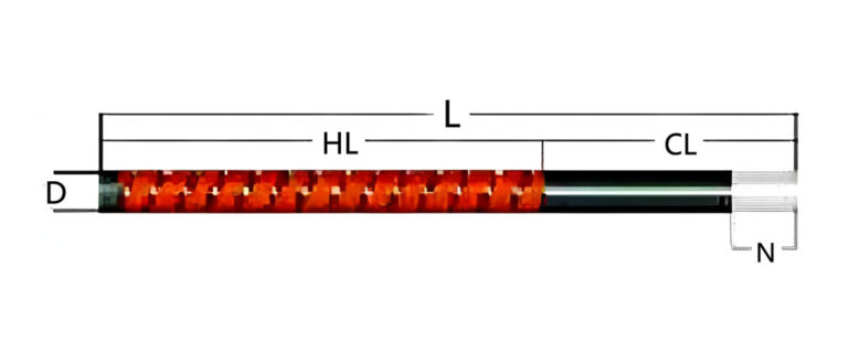
Spiral Groove
Machined spiral increases resistance per length, enabling lower current, higher voltage operation in tight spaces.

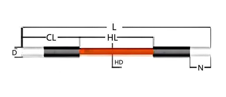
Dumbbell
Slim hot zone with robust cold ends to minimize terminal heat while preserving power density.
Custom silicon
Matched element + ceramic hardware kits for faster commissioning and repeatable installs.
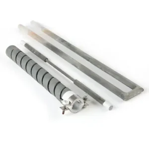
Customization Available
Silicon carbide electric heating elements (silicon carbide rod heating rods) thick end type (CD type), straight rod type (ED type), U type, W type (three-phase type), single and double thread type, right angle U type, five-section type (two heating parts, used for double-channel kilns)


- Diameters Ø8–40 mm; hot zone length 50–2,000 mm; tailored cold ends
- Element types: Straight, U, W, Spiral Groove, Dumbbell
- Optimized resistance / target current for your transformer and controller
- Protective coatings for air cycling and corrosive volatiles
- Tight tolerances for automated fixtures and uniform radiant spacing
- Matched ceramics: supports, tubes, terminal hardware, and clamps
Material Selection
We use recrystallized silicon carbide (RSiC) engineered for electrical stability at high temperature. Compared with dense SiSiC, RSiC balances porosity for emissivity and robust mechanical strength. For reducing atmospheres, we adjust processing to mitigate carburization and volatilization risks.
Operating Range
- Typical continuous: 1,200–1,500°C
- Short excursions: up to ~1,600°C
- Atmospheres: air/oxidizing, neutral, reducing*
* Application review required for sulfur-, halogen-, or silicon-bearing volatiles.
Electrical Behavior
- Resistance increases gradually with usage (aging)
- We design voltage headroom to maintain setpoint over life
- Spiral grooves allow higher resistance in compact lengths
Compliance
- RoHS & REACH conformant materials
- Full lot traceability and serialized labeling
- Certificates of conformance on request
Applications of Silicon Carbide Heating Elements
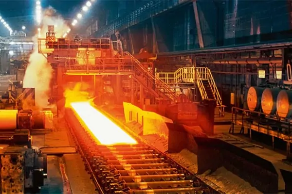
Metallurgical Industry
Used in furnaces and heat treatment ovens to process metals like steel and aluminum. SiC elements ensure even heat distribution at high temperatures.
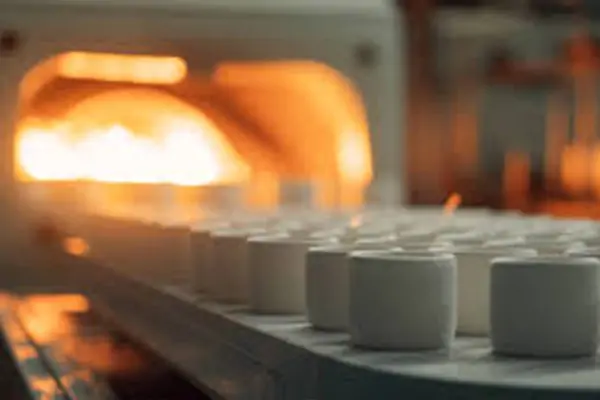
Ceramics Industry
Ideal for sintering furnaces and ceramic glaze heating, providing uniform heating for stronger ceramic products.
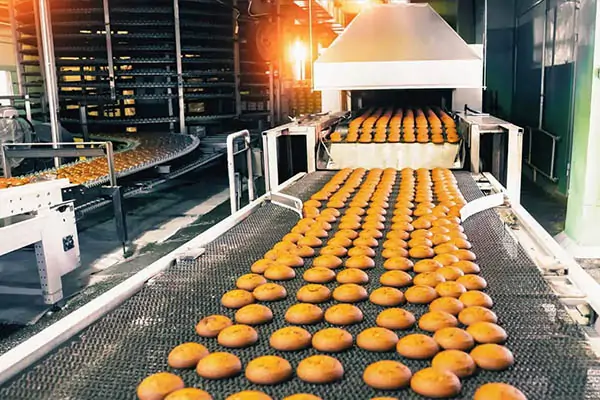
Food Industry
Employed in drying equipment and ovens to provide efficient and consistent heat for food processing.
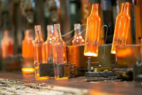
Glass Industry
Used in glass melting and annealing furnaces to ensure consistent heating and high-quality glass products.
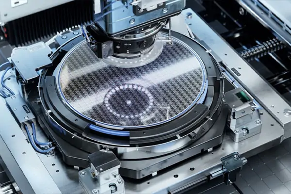
Electronics
In semiconductor and vacuum furnaces, SiC elements maintain precise temperature control for high-precision manufacturing.
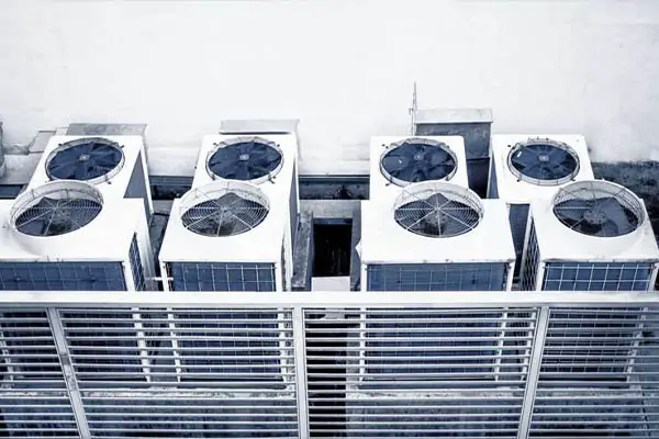
Air Heating
Common in industrial air heaters and drying machines, SiC elements provide even heat distribution for ventilation and material drying.
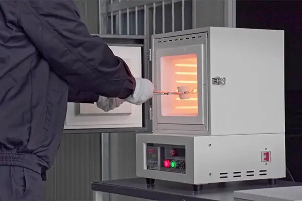
Laboratory & Research
Utilized in high-temperature laboratory furnaces for materials testing and other research applications.

Aerospace & Military
Applied in high-temperature testing and coating technologies, as well as in explosion and impact simulations.
Why customers choose our SiC Elements
Process-first sizing
We size for parts and cycle time—not just watts. You get stable recipes, fewer adjustments, and lower scrap from day one.
Retrofit-friendly
We match your transformer taps, cable length, and bus spacing so you avoid control cabinet changes.
Aging-aware design
SiC resistance drifts upward over life. We design for usable voltage headroom so you keep temperature without chasing.
What are silicon carbide heating elements?
SiC heating elements are resistive heaters made from recrystallized silicon carbide. They are self-supporting rods or shapes with a high-emissivity hot zone and low-resistance cold ends for power connection. Unlike metal heaters, they retain strength and radiance at temperatures beyond 1,200°C and tolerate a variety of atmospheres. For end users, they translate to shorter heat-up times, more available watts in a compact envelope, and simpler maintenance.
How to choose the right SiC element
Start from the process
- Required setpoint and soak times
- Load mass and heat losses (doors, exhaust, fixtures)
- Atmosphere and cycling frequency
Match your power gear
- Transformer kVA and available taps
- Controller type (phase-angle / burst-fire) and limits
- Preferred element current range (often 8–25 A/element)
Engineer for life, not day 1
- Design with voltage headroom to offset resistance growth
- Group elements in balanced sets per zone to hold uniformity
- Keep spare sets matched to installed resistance for quick swaps
Specifications by element type
| Type | Ø Range (mm) | Hot Zone (mm) | Typical Current (A) | Nominal Temp (°C) | Notes |
|---|---|---|---|---|---|
| Straight | 8–40 | 50–2,000 | 8–25 | Up to ~1,550 | Easiest retrofit; versatile mounting |
| U | 8–32 | 100–1,200 | 10–22 | Up to ~1,550 | Compact zones; two hot legs |
| W | 10–32 | 150–1,500 | 10–20 | Up to ~1,550 | Balances larger hearths |
| Spiral | 12–30 | 80–1,000 | 6–18 | Up to ~1,600 | High resistance in short lengths |
| Dumbbell | 10–30 | 80–1,200 | 8–22 | Up to ~1,550 | Cool ends, hot center |
Owner’s FAQ: Silicon Carbide Heating Elements
1.How do I break in new SiC elements?
Ramp at 2–4°C/min to 800°C, hold 30–60 minutes to stabilize resistance, then proceed to process setpoint. This reduces early drift and helps match multi-zone sets.
2.What controller settings work best?
Use phase-angle or zero-cross burst fire with soft-start enabled. Current limit per element typically 8–25 A. Enable voltage headroom so the controller can compensate as resistance rises with age.
3.How do I know an element needs replacement?
Watch for slow heat-up, maxed-out power at setpoint, or >20% resistance increase vs. installation label. Dark/cool sections in the hot zone or cracked bridges indicate end-of-life.
4.Can I mix old and new elements in the same zone?
Avoid mixing within a control zone. If unavoidable, group by similar resistance and balance currents to protect the new elements from overloading.
5.What atmospheres are acceptable?
Air/oxidizing, many neutral gases, and some reducing environments. Avoid sulfur-, halogen-, and silicon-bearing volatiles without a protective strategy—these can attack the SiC surface.
6.How should terminals be clamped?
Use clean, flat copper/aluminum clamps with firm, even pressure. Do not overtighten—crushing increases contact resistance and heat. Recheck tightness after the first heat cycle.
7.Do SiC elements need cleaning or maintenance?
Keep terminals free of scale and dust; inspect supports for ceramic wear. Do not wire-brush the hot zone—wipe gently if needed. Replace damaged hardware to maintain alignment.
8.Storage and handling tips?
Store flat in the original packaging, indoors and dry. Lift by the cold ends, not the hot zone. Avoid impacts; small chips at the hot zone can concentrate stress.
9.Warranty & returns?
We warrant materials and workmanship. If shipping damage is suspected, photograph packaging and labels before unboxing and contact us within 48 hours for a fast replacement assessment.
10.What data should I record at install?
Log each element’s serial number and resistance, transformer tap, and no-load voltage/current. This baseline speeds troubleshooting and keeps zones balanced over time.