 Skip to content
This guide is written for engineers, maintenance specialists, and technical buyers who need to understand exactly how a cartridge heater is built — not just assembled, but engineered for reliable, long‑term thermal performance. Drawing on over 15 years of hands‑on experience in industrial heating element production, I will walk you through the entire cartridge heater manufacturing process, from the physics of how a cartridge heater works through each production step, quality gate, common failure mode, and testing protocol. You will leave with the knowledge to audit suppliers, specify heaters correctly, or even set up your own production line.
How a Cartridge Heater Works and Its Internal Structure
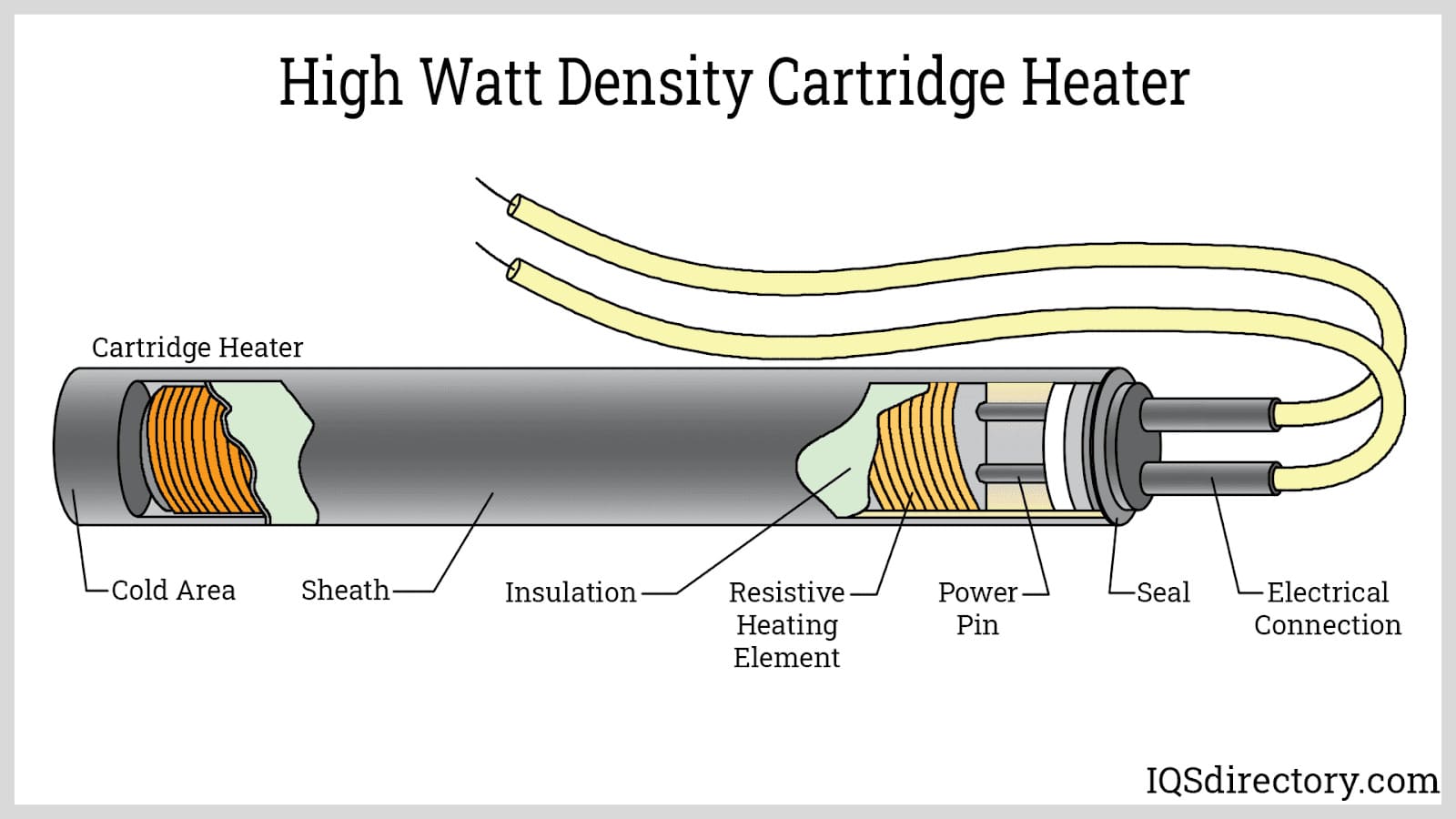
A cartridge heater converts electrical energy into heat through a resistive coil embedded inside a metal sheath, electrically insulated and thermally coupled by compacted magnesium oxide (MgO) powder. When current passes through the nickel‑chromium resistance wire, Joule heating raises the wire temperature, and the heat flows radially through the MgO layer to the sheath, then into the surrounding metal block, mold, or platen. This is why proper compaction of the MgO is the single most critical factor determining both heat transfer efficiency and dielectric strength.
Internal Structure of a Cartridge Heater
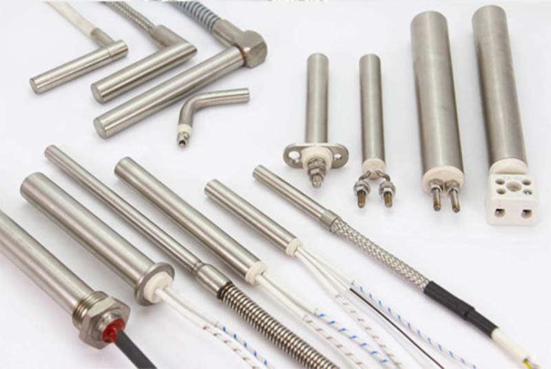
From the center outward, a typical industrial cartridge heater contains:
- Resistance coil (helical NiCr or FeCrAl wire)
- Cold pin / lead‑out rod (welded to the coil ends, bringing current to the heated zone)
- Compact MgO insulation (filled under vibration, then compacted by swaging)
- Metal sheath (stainless steel or high‑temperature alloy)
- End seal (epoxy, silicone, ceramic, or glass) at the lead exit end
- Optional: internal thermocouple, unheated cold section at one or both ends
Main Components and Their Functions
| Component | Typical Materials | Function | Key Quality Attribute |
|---|---|---|---|
| Sheath tube | 304, 316L, 310S SS; Incoloy 800/840 | Protects internals, transfers heat, withstands corrosive environments | Wall thickness uniformity, surface finish, oxidation resistance at rated temperature |
| Resistance wire | NiCr 80/20 (Cr20Ni80), FeCrAl | Generates heat via Joule effect | Uniform resistivity, precise coil pitch, no surface defects |
| MgO insulation | High‑purity electrical‑grade MgO (>96% MgO, low iron) | Provides electrical insulation and thermal conduction | Moisture content <0.1% before filling; compacted density ≥3.1 g/cm³ |
| Lead rods | Nickel, nickel‑plated copper, stainless steel | Connect power to coil; must not overheat in cold zone | Good weldability, low contact resistance, correct diameter for current |
| End seal | Silicone, epoxy, ceramic cement, glass | Prevents moisture ingress into MgO | Adhesion to sheath and leads, temperature compatibility |
Understanding this structure will make the manufacturing process much clearer.
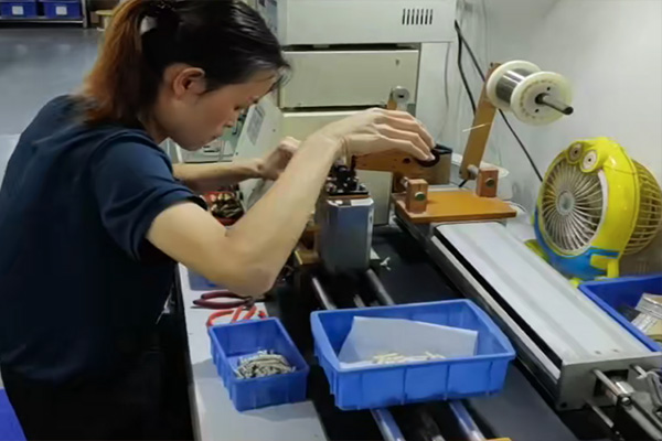
Step‑by‑Step Cartridge Heater Manufacturing Process
The following 12‑step process reflects the MgO rod construction method, commonly used for medium‑to‑high‑volume cartridge heater production. Each step is described with real‑world engineering considerations, common failure points, and quality control data.
1. Tube Cutting
Stainless steel tubes are cut to precise lengths based on the final heater length plus a machining allowance. We use automatic tube cutting machines with carbide‑tipped saw blades to ensure square, burr‑free ends.
- Typical tolerance: ±0.2 mm on length.
- Burr removal by deburring brush or vibratory tumbling.
- After cutting, tubes are cleaned to remove cutting oil and metal chips.
Shop note: Any residual cutting fluid inside the tube can contaminate the MgO rod and drastically lower insulation resistance. In our plant, tubes go through an ultrasonic wash and hot‑air dry cycle before moving to welding.
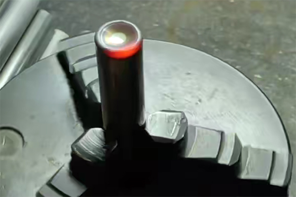
2. Bottom Welding
One end of the tube is closed with a welded disc or plug. This forms the sealed end of the cartridge heater. We use TIG welding for stainless sheaths to create a homogeneous, leak‑tight joint.
- The weld must be fully penetrated without burn‑through.
- Post‑weld, the closure is ground flush with the tube OD if required.
- A pressure test (air at 0.5 MPa under water) is performed on a sample basis to verify weld integrity.
Real‑world insight: Incomplete fusion at the bottom weld can open during swaging or thermal cycling, allowing moisture ingress. We regularly cross‑section bottom welds and etch for penetration inspection.
3. Coil Winding
Resistance wire (typically NiCr 80/20) is helically wound on a precision CNC winding machine. The coil’s pitch, length, and OD are matched to the MgO rod dimensions and the desired wattage.
- Coil OD is designed to fit snugly over the MgO rod (or inside a grooved rod) with minimal gap.
- Pitch tolerance: ±0.2 mm.
- After winding, coils are heat‑treated at 850°C in protective atmosphere to relieve winding stress and stabilize resistance.
Production experience: If a coil is stretched or compressed even slightly during handling, it can create uneven heat distribution. We store coils in individual tubes and never touch the active winding area after forming.
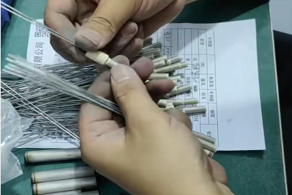
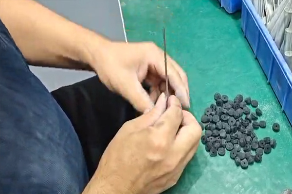
4. Magnesium Oxide Rod Cutting
Pre‑formed, high‑purity MgO rods are cut to length. These rods have a central bore to accommodate the lead rod and are sometimes grooved externally to hold the resistance coil in place.
- MgO rods must be stored in a dry environment (relative humidity <30%).
- Cutting is done with a diamond saw or precision grinder to avoid chipping.
- Rods are baked at 300°C before assembly to remove any absorbed moisture.
Critical point: MgO rods, while less prone to settlement than powder, still absorb moisture. A rod left out on a humid shop floor for an hour can cause a heater to fail a hot IR test. We measure the weight of sample rods before and after baking to confirm dryness.
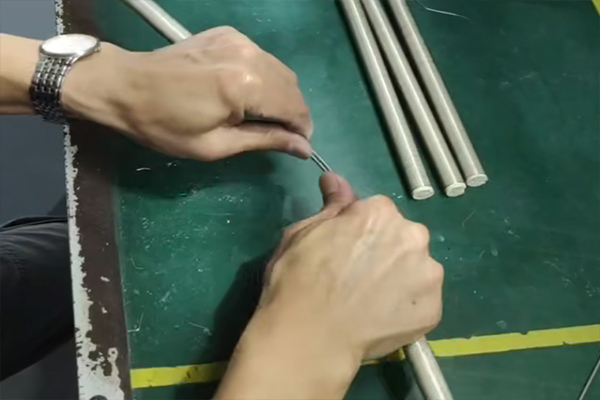
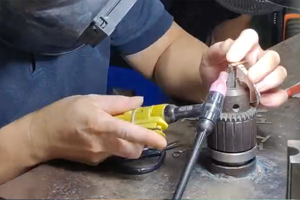
5. Inserting Lead Rod
The nickel or stainless steel lead rod is inserted through the central bore of the MgO rod. The resistance coil is then positioned over the MgO rod, and the coil ends are welded to the lead rod at the cold‑hot junction point.
- The weld must be concentric; any protrusion will create a stress riser during swaging.
- The entire coil‑MgO‑lead assembly is then tested for cold resistance and visually inspected.
Engineering detail: We use a jig to hold the assembly in alignment. An off‑center weld that touches the MgO rod’s inner wall can cause a latent short that only appears after several thermal cycles, once MgO shifts slightly.
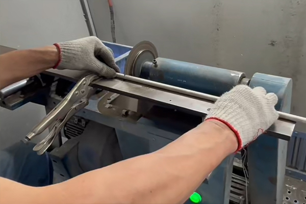
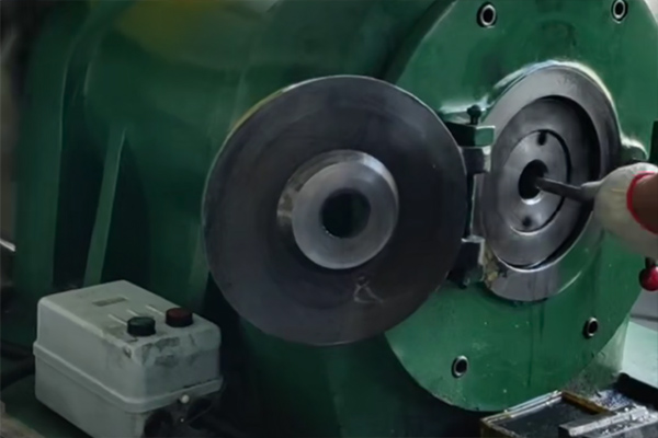
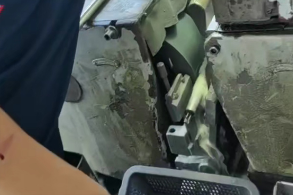
6. Tube Swaging
The assembled coil‑MgO‑lead insert is pushed into the sheath, and the entire assembly is passed through a rotary swaging machine. The hammering action reduces the tube OD by 15–25%, compacting the MgO rod tightly against the coil and sheath.
- Multi‑pass swaging: typically 3–5 passes, each reducing diameter by 0.3–0.6 mm.
- Swaging dies are lubricated and inspected every 500 cycles.
- Final OD tolerance: ±0.03 mm for diameters up to 16 mm.
Real‑world observation: If the MgO rod was slightly undersized or had a void, swaging will not fully compact that area — a hot spot will appear during operation. We sometimes use X‑ray inspection for high‑reliability batches to check MgO integrity.
7. Polishing
The swaged tube surface may show die marks or slight roughness. Polishing with abrasive belts or centerless polishing machines achieves the specified surface finish (typically Ra 0.8–1.6 µm).
- Polishing also removes minor oxidation and prepares the surface for optional passivation.
- Over‑polishing can reduce wall thickness beyond tolerance, so operators measure OD before and after.
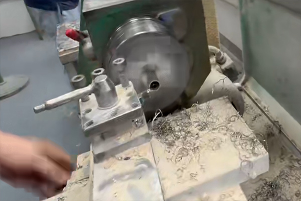
8. Tube Machining
The open end of the tube is machined to final length, and any required features are added: threads, grooves for O‑rings, flats for wrenching, or step diameters.
- CNC lathe operations are used for consistency.
- Machining after swaging and polishing ensures that all features are true to the final OD.
Practical tip: Any machining at this stage must avoid cutting into the MgO. We leave a cold end length of at least 5–10 mm beyond the last coil turn.
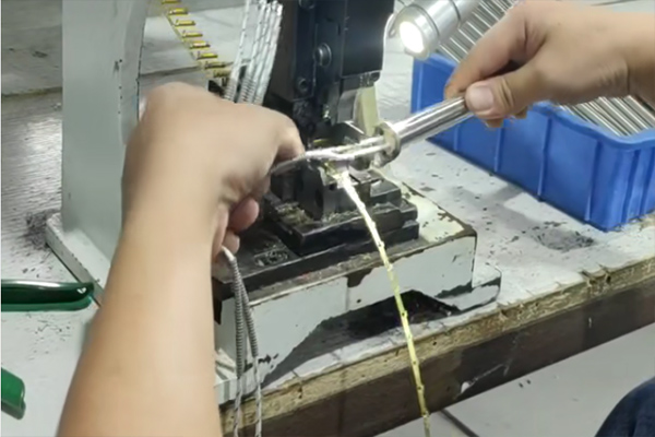
9. Sealing
The lead exit end is sealed to prevent moisture from penetrating the MgO insulation. Seal material selection depends on the heater’s rated temperature:
- Low‑temp (<200°C): two‑part epoxy or RTV silicone.
- Mid‑temp (200–400°C): ceramic cement.
- High‑temp (>400°C): glass‑to‑metal seal or hermetic ceramic bushing.
After sealing, insulation resistance is measured again. Any drop >10% from the pre‑seal value indicates moisture incursion or solvent attack, and the heater is baked and retested.
10. Flange Bracket Welding
If the heater requires a mounting flange or bracket, it is welded to the sheath at this stage. TIG or laser welding is used to minimize heat input and distortion.
- The flange position is set using a fixture to ensure the correct immersion length.
- Welds are visually inspected and, on high‑pressure applications, dye‑penetrant tested.
11. Lead Wire Connection
High‑temperature lead wires (fiberglass‑insulated, PTFE, or silicone) are crimped or brazed to the exposed lead rods. A strain relief spring or fiberglass sleeving is added over the connection.
- Crimp connections are pull‑tested to a minimum of 50 N.
- Lead wire length and stripping dimensions are verified against the customer drawing.
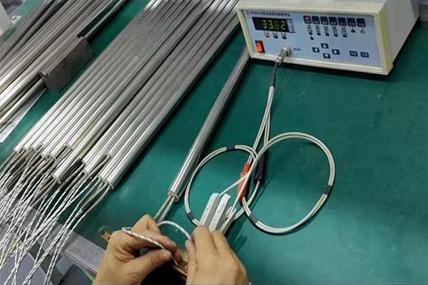
12. Testing Process
Every cartridge heater undergoes a full electrical and dimensional inspection. As discussed in the quality section, our standard tests include:
| Test | Acceptance Criterion | Instrument |
|---|---|---|
| Insulation resistance (cold) | ≥ 100 MΩ at 500 V DC | Megohmmeter |
| Dielectric withstand (hi‑pot) | 1500 V AC, 1 min, <0.5 mA leakage | AC hi‑pot tester |
| Cold resistance | Within ±5% of rated wattage | Micro‑ohmmeter |
| Dimensional check | OD, length, flange position per print | Calipers, go/no‑go gauges |
| Thermal uniformity (sample) | ≤ 10°C variation over heated length | Thermal camera |
For critical applications, we also run a 2‑hour powered burn‑in while monitoring current and temperature, ensuring no drift or hot spots develop.
Common Manufacturing Challenges and Real‑World Troubleshooting
Even with the robust MgO rod process, certain defects can occur. The table below draws on hundreds of root‑cause analyses from the production floor.
| Observation | Most Likely Root Cause | Corrective Action |
|---|---|---|
| Low cold IR after swaging | Moisture in MgO rod or poor pre‑bake | Increase rod baking time/temperature; verify storage humidity |
| Hot IR failure (drop below 2 MΩ) | MgO rod cracked during swaging, allowing moisture path | Reduce swaging reduction per pass; X‑ray suspect rods |
| Localized glowing spot | Uneven coil‑to‑rod contact; rod chipped during cutting | Check rod groove quality; improve coil winding tension control |
| Resistance drift after 50 h | Incomplete coil annealing; poor lead‑rod weld | Raise coil annealing temperature; tighten weld parameters |
| Sheath bulging | Over‑temperature causing MgO expansion; trapped gas | Verify watt density; improve pre‑bake to drive off volatiles |
| Lead seal cracking | Thermal expansion mismatch; insufficient strain relief | Use flexible lead wire and proper spring guard |
<a id="standards"></a>
Quality Assurance and Industry Standards
We align our manufacturing and testing with the following standards:
- IEC 60519‑1 – Safety in electric heating installations.
- JB/T 2379‑2016 – Metal tubular heating elements (Chinese standard for MgO‑insulated heaters).
- ASTM B344 – Specification for NiCr heating element wire.
- UL 1030 – Standard for sheath‑type heating elements, where required.
All measuring instruments are calibrated traceable to national standards, and we maintain a first‑article inspection report for each new heater design.
<a id="build-vs-buy"></a>
When to Build vs. When to Buy
Setting up an in‑house line with tube cutting, bottom welding, coil winding, swaging, and a full electrical test bench demands significant capital. Unless you are producing over 20,000 cartridge heaters per year of similar configurations, purchasing from a qualified manufacturer is more cost‑effective. Use the knowledge from this guide to write a tight specification: require certified test reports, define maximum watt density, and request hot IR testing if reliability is critical.
<a id="faq"></a>
Frequently Asked Questions
(The FAQ section remains largely unchanged as the fundamental operation and application of cartridge heaters are independent of the specific internal construction method. Slight edits have been made where necessary to reflect the MgO rod process.)
1. What is the maximum operating temperature of a standard cartridge heater?
Maximum sheath temperature depends on the material. A 304 stainless steel sheath can operate continuously up to about 760°C. Incoloy 800 sheaths can reach 870°C. The internal coil temperature is higher; NiCr 80/20 wire is rated up to 1200°C, but for long life, keep the watt density appropriate.
2. Can I bend a cartridge heater after manufacturing?
Yes, if the heater has been fully annealed after swaging. Bending an un‑annealed heater will crack the sheath. Bend only in the cold section (unheated zone), with a minimum bend radius of 2× the sheath diameter.
3. What is the difference between a swaged and an unswaged cartridge heater?
An unswaged heater has uncompacted MgO insulation (powder or loose rod), resulting in poor heat transfer and low dielectric strength. A swaged heater has its MgO mechanically compacted, achieving 3–5 times better thermal conductivity and consistent insulation resistance. All industrial cartridge heaters today are swaged.
4. How do I select the correct watt density?
Watt density (W/cm²) depends on the application. For a precisely bored metal block with tight fit, 15–25 W/cm² is typical. For heating air or loose fit, keep it below 5 W/cm². Always consult a manufacturer’s watt density chart and consider the fit clearance.
5. Why does my cartridge heater fail after only a few weeks?
Common causes: moisture in the MgO, uneven coil‑to‑MgO contact causing hot spots, exceeding recommended watt density, or using a sheath material not suited to the environment. A teardown analysis can usually pinpoint the failure.
6. Can I cut a cartridge heater to length?
No. Cutting will sever the resistance coil or expose live parts. Order a custom length — the manufacturing process easily accommodates variations.
7. What lead wire insulation is best for high temperatures?
PTFE for up to 260°C, silicone‑fiberglass for up to 480°C, and pure fiberglass with stainless steel overbraid for higher. Ensure the insulation rating matches the lead‑end temperature.
8. How should I test a cartridge heater before installation?
Visually inspect for damage. Measure insulation resistance with a 500 V megger (should be ≥50 MΩ). Measure resistance and compare to nameplate wattage (±5%). If IR is low, bake the heater at 120°C for a few hours and retest.
9. What is the advantage of NiCr 80/20 over FeCrAl wire?
NiCr 80/20 is ductile, weldable, and has a stable resistance‑temperature curve. FeCrAl can withstand higher temperatures but becomes brittle after first use, making it unsuitable for heaters that may be bent. For most industrial cartridge heaters, NiCr 80/20 is preferred.
10. How do I store unused cartridge heaters?
Keep them in a dry, clean area in sealed plastic bags with desiccant. Before use, always check insulation resistance; a low reading can often be restored by baking.
